Weld Symbol Chart Video Bokep Ngentot
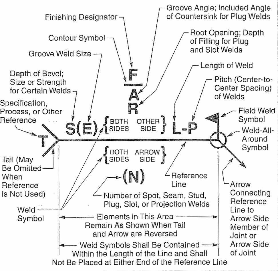
The weld symbol always includes. An arrow line. A reference line. A dashed line. A symbol. Note: Weld symbols on the full reference line relates to welds on the near side of the plate being welded. Weld symbols on the dashed line relates to weld on the far side of the plate. If the welds are symmetrical on both sides of the plate the dashed.

Welding Symbols Chart Printable Welding table, Welding projects, Welding
A welding symbol is a picture with multiple parts that contain information to inform the welder about how to proceed. This section aims to break down the structure of the welding symbol, making it easier to digest and understand. Basic Structure of a Welding Symbol An empty welding symbol © weldguru.com - Image usage rights
9 Basic Steps to Read Welding Symbols WELDING ANSWERS
Home » Welders A Complete Guide to Weld Symbols: How to Read Them We explain the basics of weld symbols: their structure, what different lines mean, and what standards there are. By Christopher McDonagh Reviewed By Thomas Garcia Last updated: August 12, 2023 Weld Zone is reader-supported.
Weld Symbols Chart American Welding Society DWG file Autodesk_AutoCAD
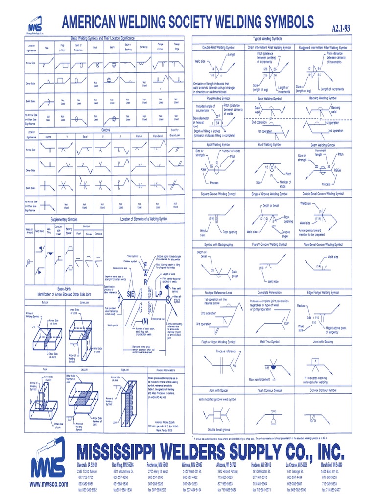
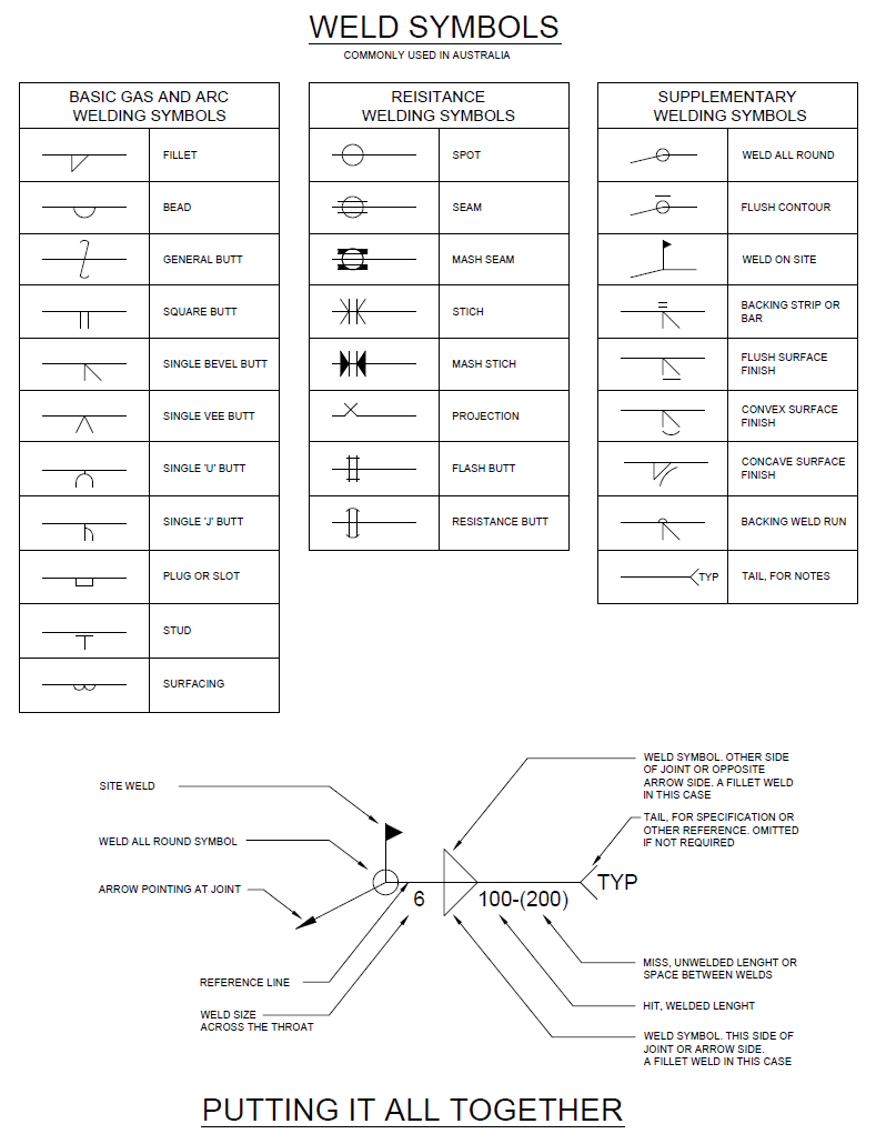
AWS Welding Symbol Chart (desk Size) AWS Welding Symbol Chart (Wall Size) On the other hand, the welding symbol is constructed using the basic weld symbol and additional supplementary information. An example of a welding symbol (in this case a fillet weld) is given in the below picture:

Welding Symbols & their description MADLAB ENGINEERING
The weld symbol distinguishes between the two sides by using the arrow and the spaces above and below the reference line. The side of the joint to which the arrow points is known as the arrow side, and that weld's instructions are given below the reference line.
Welding Symbols Chart Printable
ˇˆ˙ˇ˝ ˛˚ ˘ ˇ ˆ ˙ ˘ ˇˇˆ. Title: A21-desk.fm Author: Default Created Date: 7/25/2001 8:48:45 AM
Basic Welding Symbols Weld My World
1. Scope This standard outlines the method of presenting welding symbols. It is applicable to both metal fusion welding and resistance welding. 2. Normative References GB/T 5185 Designation of Metal Welding and Brazing Methods in Drawings; GB/T 12212 Technical Drawings - Dimension, Proportions, and Simplified Representation of Welding Symbols. 3.

Is there a specific way to detail different welding types on drawings
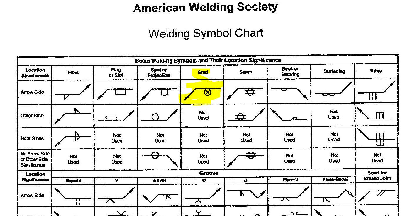
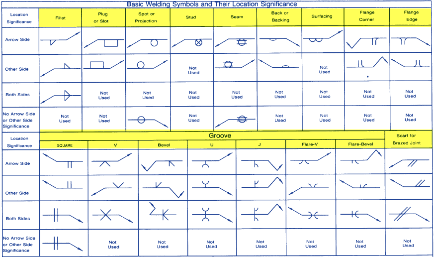
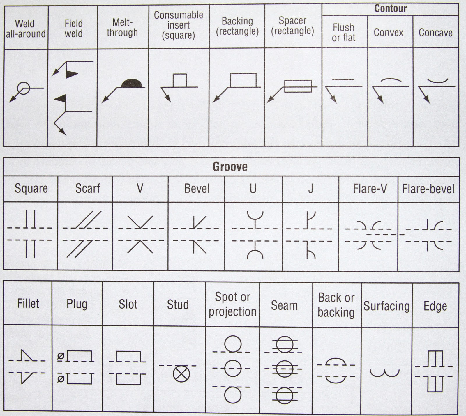
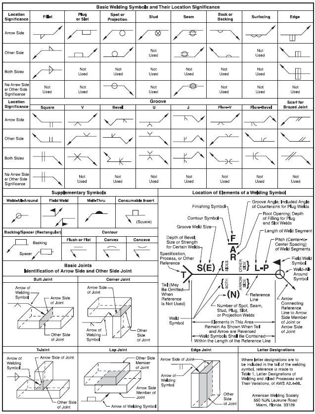
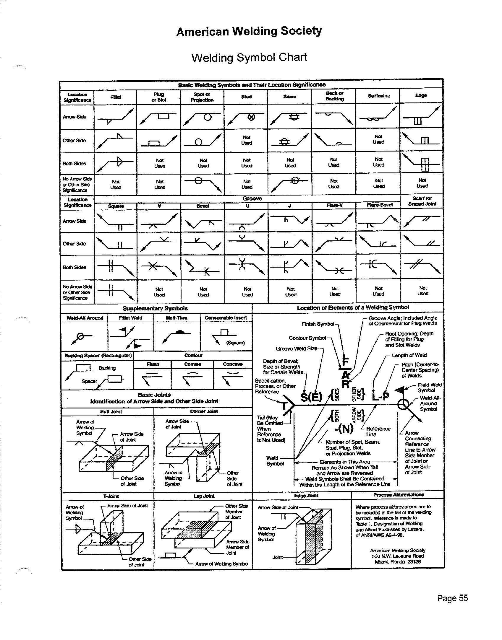
Weld symbols are used to indicate the welding processes used in metal joining operations, whether the weld is localized or "all around", whether it is a shop or field weld, and the contour of welds.. welding symbols chart. For more information, see ANSI/AWS A2.4, Symbols for Welding, and Nondestructive Testing. Welding symbols chart.
Weld Symbols Chart
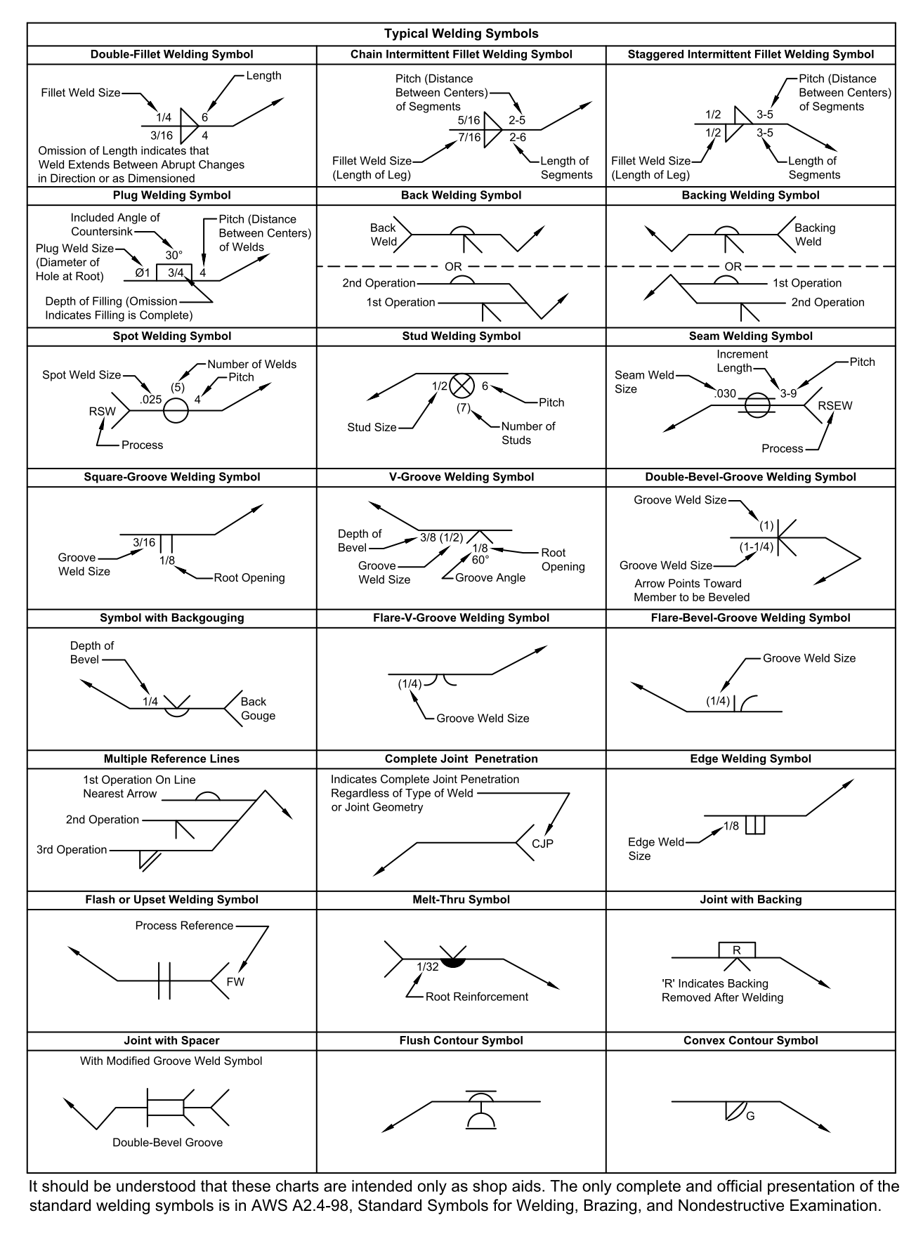
Welding Symbol Chart mplso2.com It should be understood that these charts are intended only as shop aids. The only complete and official presentation of the standard welding symbols is in AWS A2.4, Standard Symbols for Welding, Brazing, and Nondestructive Examination. 1-800-236-3902
How to Read Welding Symbols? » Weld Hacks
It usually involves preparing the edge pieces to form one of the groove weld shapes like V, bevel, U, J, Flare V, Flare bevel or no preparation at all with square edges to form a square groove. Plug/slot - These are welds used to form overlapping joints using holes in which welds get deposited. Flange or edge welds.
Printable Welding Symbols Chart
A weld Symbol defines the type of geometry for the welding joint. E.g. a Fillet Weld, a bevel or square butt, etc. A Welding Symbol is partial without a Weld Symbol. So, Weld Symbol supplements a Welding Symbol to provide full details about the welding requirements. So basically, the weld symbol is a part of the welding symbol.
Engineering Know How American Welding Society Welding Symbol Chart
Created Date: 1/13/2012 8:35:12 AM
Structural Drafter
1. The Base Platform This symbol is a simple platform for displaying the characteristics and surrounding details for your welds. It has three parts: The arrow line: points to the general location of the weld. The reference line: this is where the details are placed about the type of weld and the specific location.

Weld Symbol ?? Construction Contractor Talk
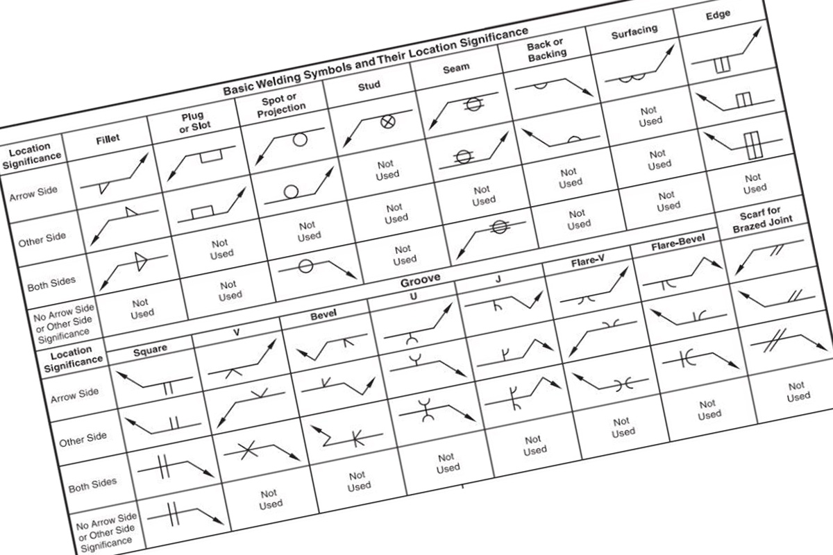
The American Welding Society has a very nice chart detailing these symbols. Below is a section of it. Going forward we will stay with Fillet welds since the following information is displayed differently depending on the type of weld joint. Download this guide for FREE
Printable Weld Symbol Chart
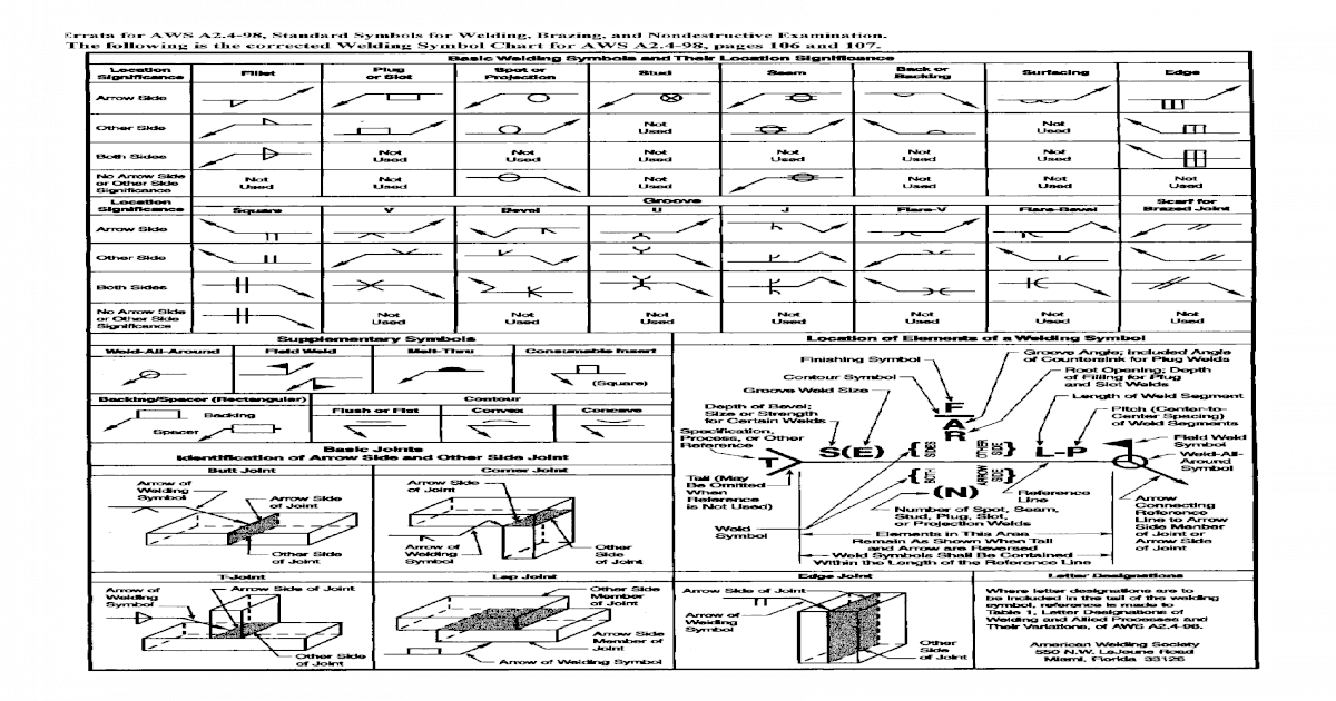
A chart of the supplementary symbols. A drawing of the location of elements of a welding symbol and how to put it all together. Isometric views of basic joints identification of arrow side and other side joint examples. Typical welding symbols examples. Download an AutoCAD DWG version of the Weld Symbols Chart
Explanation of a welding symbol The Piping Engineering World
Here are the main types of welds and their corresponding symbols: Fillet Weld: This is the most common type of weld, used when joining two surfaces at a right angle. The symbol looks like a right triangle. Groove Weld: This type of weld is used when a joint needs to be completely penetrated. The symbol varies, depending on the geometry of the.
