Pressure relief valve symbol icon Royalty Free Vector Image
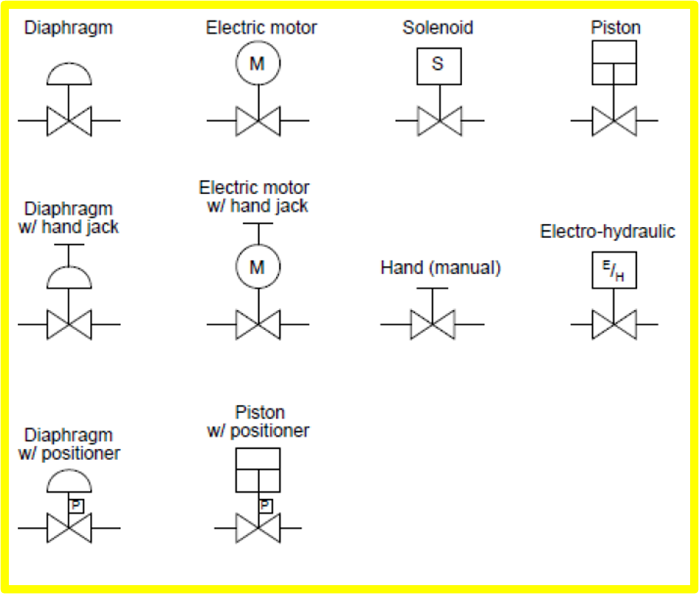
A pressure relief valve is a NC (normally closed) type safety valve which operates when system pressure increases above a maximum working pressure. The normally closed position is indicated by the arrow away from the center line. The dashed line indicates that the system pressure acts against spring force for valve actuation.

Pressure Relief Valve Symbol Schematic
assured by the presence of an ASME Code Symbol Stamp and the letters NB on each pressure relief valve nameplate. Lower set pressures are not addressed by either the National Board or ASME; however, capacities. pressure relief valve orifice area and maximum available flow. This sizing program is a powerful tool, yet easy to use. Its many

Pressure Relief Valve Schematic Symbol
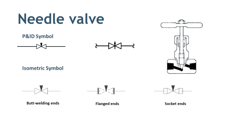
P&ID Symbols for Valves. Many types of valves are required in a process plant for flow regulation or on/off purpose. Type of valve employed depends on nature of fluid, flow control required, operating pressure and temperatures as well as surround atmosphere. Here is a list of symbols for various types of valves used in process industry.

Valve Symbols in P&ID Ball Valve, Relief Valve and more
Pressure relief valves are effectively a safety mechanism for the boiler and central heating system To relieve pressure on the system when it gets too high. as you can see from the image below, pressure relief valves are set at a specific pressure level, often 3 bar, like this one below: PRV Valve - Pressure Rating of 3 bar
Transparent Safety Icon Png Pressure Relief Valve Symbol , Free Transparent Clipart ClipartKey
December 17, 2021 by Haresh Bambhania What is Pressure Relief Valve? A pressure relief valve (PRV) or relief valve is a type of safety valve used to control or limit the pressure in a system; pressure might otherwise build up and create a process upset, instrument or equipment failure, or fire.
Pressure Relief Valves An Exploration of Industrial Technology
May 25, 2022 by Robert McGillivray Figure 1: A process and instrumentation diagram The Process and instrumentation diagram, commonly known as a P&ID, shows the connections between process equipment. The diagram indicates the flow directions, safety and control measures, and pressure ratings of a system through visual symbols.

Mechanical Drawing Symbols Design elements Valves Design elements Fluid power valves
The symbology for the identification of the measurement and control instrumentation on the flow and process diagrams and on the P&ID (Piping & Instrument Diagram), commonly called P&I (Piping & Instrumentation), is generally compliant with the Standard ISA (Instrumentation Society of Automation) identified as S.5, that is composed of identificat.
Glossary of ISO Hydraulic Schematic Symbols and Their Meanings
The most widely used type of pressure control valve is the pressure-relief valve because it is found in practically every hydraulic system. Schematic diagram of simple relief valve is shown in Fig. 1.1 and three-dimensional view is shown in Fig. 1.2. It is normally a closed valve whose function is to limit the pressure to a specified maximum.

Types Of Valves, Their Functions And Symbols Engineering Discoveries
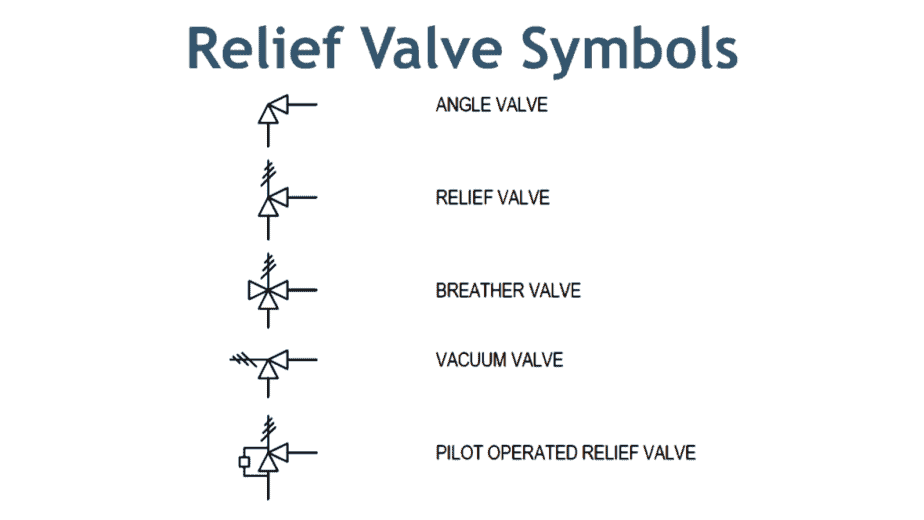
Symbols of Pressure Relief valve used in different Instrumentation diagram. 1.Pilot operated, balanced piston relief valve 2.Direct-acting relief valve 3.Non-adjustable direct-acting relief valve 4.Direct-acting relief valve, CE marked 5.Fast-acting, pilot operated, balanced piston reli. Industrial Automation, PLC Programming, scada & Pid.

Types of Valves (P&ID symbols) ? REFINERY OIL AND GAS
Figures 18-21 and 18-22 show a symbol for a remote relief valve setup. Figure 18-21 shows the simplified symbol; Figure 18-22 shows the complete symbol. All pilot-operated relief valves have a vent port. The vent port tees into the pilot line that connects system pressure to the direct-acting relief valve's pilot section.
Pressure Relief Valve Schematic Symbol
In Hydraulic Symbology 101 ( read it here first ), I covered the basic square used for pressure valves and also showed the most stripped-down versions of the two most commonly used pressure valve symbols, the relief valve and the pressure reducing valve.
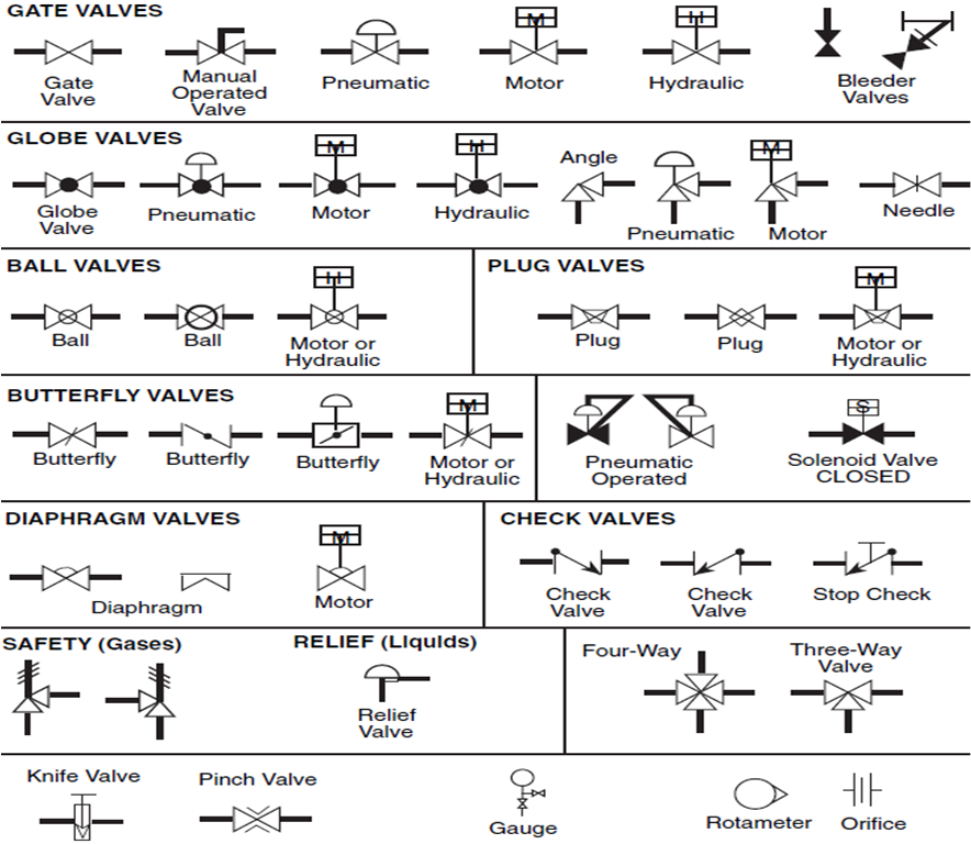
Valve Sign Symbols The Engineering Concepts
Relief valve (RV): A valve is used on a liquid service, which opens proportionally as the increasing pressure overcomes the spring pressure. Safety valve (SV): Used in gas service. Most SVs are full lift or snap-acting, in that they pop completely open.
Control valve symbols in P&id Valves Industrial Automation, PLC Programming, scada & Pid
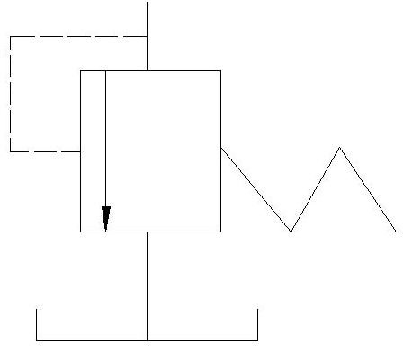
Pressure Relief Valve Symbols Date: 25-03-2022 Hydraulic Tips Hydraulic pressure relief valve symbols In the below image, the top symbol shows a simple, direct operated pressure relief valve. Note how the arrow is shown in its deactivated position e.g. with the spring force higher than the pressure in the pilot.
What is Pressure Relief Valve? Working Principle, Symbol, Diagram, Types & Function
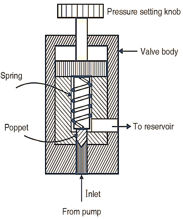
The top symbol indicates a simple, direct operated pressure relief valve. Note how the pilot pressure (shown by the dashed line) comes from the supply line, upstream of the valve. This indicates that as the pressure before the valve increases, it pushes the arrow against the spring and relieves the pressure in the direction of the arrow.
Pressure reducing regulator valve symbol icon Vector Image
The thrust of the spring can be adjusted by the adjusting screw. Simple Pressure Relief Valve. Case 1: When the inlet pressure is insufficient to overcome the spring force, the ball remains at its seat, and the valve is closed. In this case, the flow will go into the hydraulic system. Case 2: When the inlet pressure is enough to overcome the.

DIFFERENCE BETWEEN PRESSURE REDUCING VALVE AND PRESSURE RELIEF VALVE ENGINEERING APPLICATIONS
A pressure relief valve is a safety device used for protecting the system from excess pressure by diverting the flow of fluid back to the tank. During working, the valve is closed by a poppet by the force of a stiff compression spring to stop the fluid flow. The spring force can be adjusted.